PowerMaster General Information
General Information Webpage for the Power Master
IMPORTANT NOTE: Do not try to install firmware or software for the Power Master II into an old Power Master (A.K.A: Power Master I) or vice-versa. The download links available on this webpage are for one or the other model. Scroll down to the Downloads Section and please BE CAREFUL WHEN SELECTING THE DOWNLOADING LINK.
Features
- ALC-1 - ALC protection option, shuts down your transmitter fast but yet allows ALC normal operation
- FASTEST Bar graph on the Market, makes tuning an amp or a tuner a joy, faster than an analog meter. So fast it can catch the first "dit" at 99 WPM and even show you if your rig has a RF spike problem. Why mess around with other meters that have have had display failures?
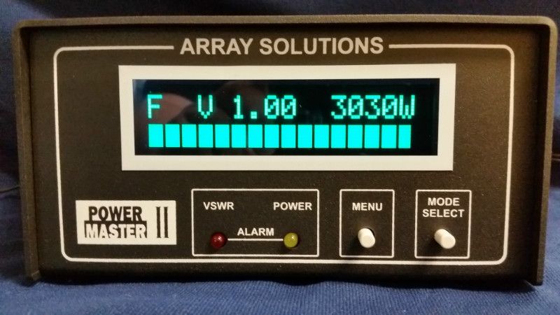
- Displays VSWR, Power, and Bar graph at the same time.
- Support for vision impaired hams via www.hampod.com
- Runs with or without a PC connected to it. That means there are no programming hassles and issues setting this meter up.
- Runs right out of the box.
- Accuracy typically better than +/- 3% over frequency and temperature ranges
- Peak Hold Modes – programmable for fast (0.5 sec), medium, slow, and Long ( 5 sec) for CW, SSB, data, FM, whatever you're sending!
- Two Models – 3 kW and 10 kW - standard coverage is 160 through 6 m (1.8 to 54 MHz)

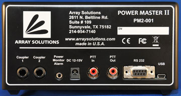
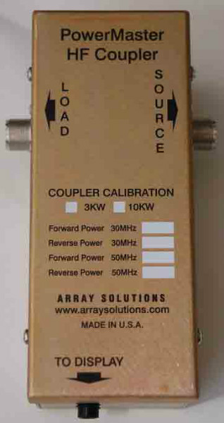
- Separate Display and Coupler/Sensor boxes– Sensor can be remotely located at your amp or in your mobile unit this also keeps the high power cables away from your radios, audio equipment, PCs etc. No nasty RF cables on top of your desk or radio to cause RFI and other clutter issues! The coupler is using DC only, no RF is sent to the meter. A good thing!
- Remote use, even 100 feet of cable between sensor and display has no drop in power measurement - None! -
- Multiple couplers on one display - the PM II supports two couplers without any external adapters.
- VSWR Alarm – programmable trip point, LED and Relay – Can shut down your amp fast!
- Power Alarm - programmable trip point, LED and Relay - Alerts you that your amp has tripped out
- Alarms can maintain until manually reset, or you can program an auto alarm reset
- Bar Graph – Operates in two modes, Auto Ranging Power and VSWR you can peak your amp sending dots or talking into a mic, or dip your VSWR with your tuner using dots. Easy on the tubes and efficient.
- Bar Graph in Power mode – Auto Ranging in user selectable ranges – Easy to read
- Large LCD Display – Easy to read even in bright sunlight - low energy consumtion
- Programmable from front panel or via USB or RS-232 – Even display your call letters in it too!
- Free Application for your PC - Will allow remote user’s full use of meter even on the internet
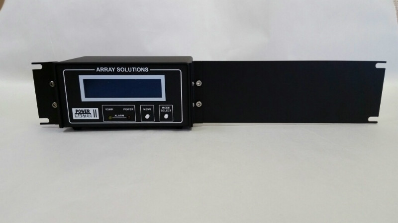
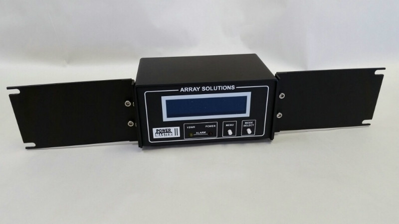
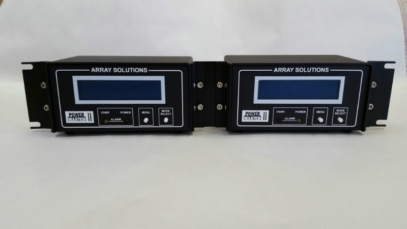
- All Metal Boxes – Rack Mount Options available, 1 or 2 units in a 19” 2U panel
- Choice of connectors, SO-239, N-type, and 7/16 DIN
- Display Head Size 7” X 3-3/4" Face, 4-1/2” Deep
- And did we mention the best support you can get from us and our user group?
- Interface to any RS-232 Port or USB port
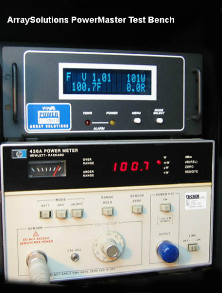
NIST traceable calibration standard
Set up any of the functions of the meter which include:
- Call letters or other alpha numeric message – 16 characters long (examples above have "Array Solutions")
- Set up default VSWR alarm trigger or turn it off
- Set up default Power alarm trigger or turn it off
- Mode of operation
- Fast, medium, slow
- Bar graph
- Auto range scale
- Peak, Peak plus reverse
- Bar graph mode VSWR or Power
- Forward power
- Reverse power
- VSWR
- Data in alpha numeric / bar graph – Both on screen
- Peak hold as well as real time power in bar graph
- VSWR Alarm
- Power Alarm
- Hooks to allow access to the data from another application like a contest logging program
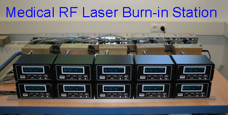
Critical Testing Applications
Why not buy the same VSWR Power meter that is used by industry for critical monitoring functions?
19-inch Rack mounting kits are available
.jpg)
PowerMaster VHF coupler with 7/16DIN connectors
Downloads
PowerMaster-II downloads
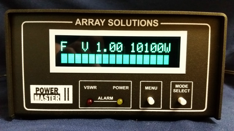

Note the logo at the bottom left corner of the front panel to identify the
PowerMaster II, it most have the "II" on the logo, otherwise it is a PM1.
Software files for PM-II
Latest software update for your Power Master II
. This is an enhancement software for the PM-II. To install, remove the current version of PowerMaster II Basic. Double click on setup.exe. The enhancements are described on the pdf files downloaded along the update, and are the following:
- Support for multiple instances of PM on same computer. Start with ini=name_of_ini_file .
Firmware files for PM-II
Latest Firmware October 25, 2021 NOTE: Download latest firmware and use the File->Firmware Update selection in the Power Master II software
Power Master Application Notes for SO2R (Single Operator Two Radio) operation, click here
PowerMaster-I downloads (Or just PowerMaster or the old PowerMaster)
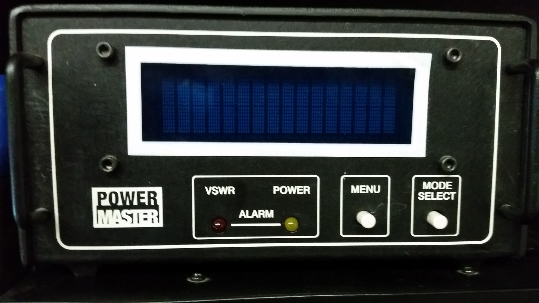

Note the logo at the bottom left corner of the PoweMaster display to identify
the PowerMaster-1 or PowerMaster, there is no "II" on the logo
NOTE: The following links have the CD files and the firmware files ONLY FOR THE ORIGINAL POWER MASTER:
Downloads for PM-I
PM-1 Software and guide for remote operation
PM-1 User Manual
Firmware files for PM-I
IMPORTANT: If in your PM-I display you do have the "Refresh Display" option, you don't need to update the firmware.
Click here to download the Firmware Updater NOTE: " DOWNLOAD "Latest Firmware", AND THEN USE "NEXT" INSTEAD OF "GET UPDATE" ON FIRMWARE UPDATE PROGRAM
Click here to download the PowerMaster-I firmware for 3 kW couplers
Click here to download the PowerMaster-I firmware for 10 kW couplers
NOTE 1: Do not ATTEMPT to install this sofware and or firmware for the PM 1 into a PM 2
NOTE 2: Do not ATTEMPT to install the 3 kW firmware on a PowerMaster-1 that has a 10 kW firmware or vice-versa.
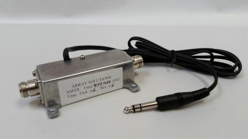
VHF & UHF Couplers for the Power Master and Power Master II
Models: VHF-1.5K (2m), VHF-1.5K-2 (1.35m), UHF1.5K (440-450MHz), UHF-1.5K-2 (420-440MHz)
VHF and UHF Couplers Installation and Operation Manual
 CURRENTLY UNAVAILABLE
 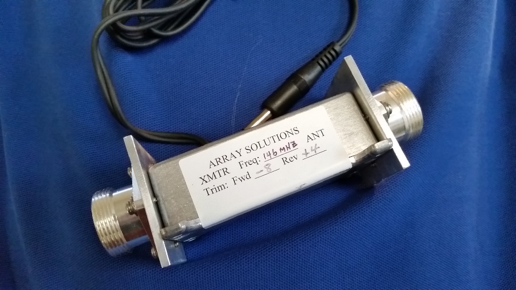 CURRENTLY UNAVAILABLE
1. INTRODUCTION
The Array Solutions VHF and UHF couplers extend the frequency range of the PowerMaster Series Digital RF Power & VSWR Indicator to the 2m, 1.35m and 70cm amateur bands. The VHF and UHF series couplers are precision dual directional couplers. They have dual pickup loops to provide simultaneous forward and reflected power measurements.
2. INSTALLATION PROCEDURE
The PowerMaster VHF and UHF couplers may be inserted in the antenna feedline at any convenient point. The end of the coupler that is marked “ANT” is connected to the feedline that goes to the antenna. The other end is connected to the transceiver or linear amplifier.
The cable with 1/4” phone plug is plugged into the PowerMaster or PowerMasterII display unit.
To use the PowerMaster with any coupler, first verify that the latest firmware is loaded in the PowerMaster. Firmware may be downloaded from the Array Solutions web site: www.arraysolutions.com/manuals.htm
COUPLER MODEL FREQUENCY MHz
- VHF-1.5K 144-148
- VHF-1.5K-2 220-225
- UHF-1.5K 440-450
- UHF-1.5K-2 420-440
Enter the trim factor for both forward and reflected power, The trim factors are marked on each coupler. Refer to the PowerMaster/PowerMasterII Manual for instructions on setting the trim factors.
3. OPERATION
With the proper firmware loaded, operation and display features are the same as with a HF coupler. Refer to the Array Solutions PowerMaster Series Digital RF Power Meter manual for instructions on the PowerMaster Series operating procedures and display features.
4. CARE AND MAINTENANCE
There is no maintenance required for the VHF/UHF couplers. There are no user adjustable components inside the couplers. Do not remove the coupler cover or disassemble it in any way as calibration will be lost.
Avoid anything that would apply a significant shock to the couplers such as dropping them or hitting them with any object. A mechanical shock can cause movement in the pickup loops which may affect the accuracy of the couplers.
Should you suspect a problem with your VHF or UHF coupler call Array Solutions for instructions on how to return the unit for repair and calibration.
5. SPECIFICATIONS
MODEL VHF-1.5K (2m) and VHF-1.5K-2 (1.35m)
- Frequency Ranges: 144-148 MHz or 222-225 MHz
- Line Impedance 50 ohms nominal
- Insertion Loss 0.05 dB or less
- Line Connections N-type Female (UG-5 ), UHF ( SO-239 ) optional
- Power Range: 1 - 1500 watts
- Directivity: >25 dB typical 144-148 MHz, >22 dB typical 222-225 MHz
- Accuracy: +5% of reading
MODEL UHF-1.5K and UHF-1.5K-2
- Frequency Range 440-440 MHz and 420-440 MHz
- Line Impedance 50 ohms nominal
- Insertion Loss 0.1 dB or less
- Line Connections Type N Female (UG-58)
- Power Range: 1 - 1500 watts continuous
- Directivity: >23 dB typical
- Accuracy: +5% of reading
For the Latest Power Master II Software, click here
For the VHF and UHF Couplers Manual, click here