SAL Mark II antenna general information page
Shared Apex Loop - SAL antenna general information, tips, related links and downloads.
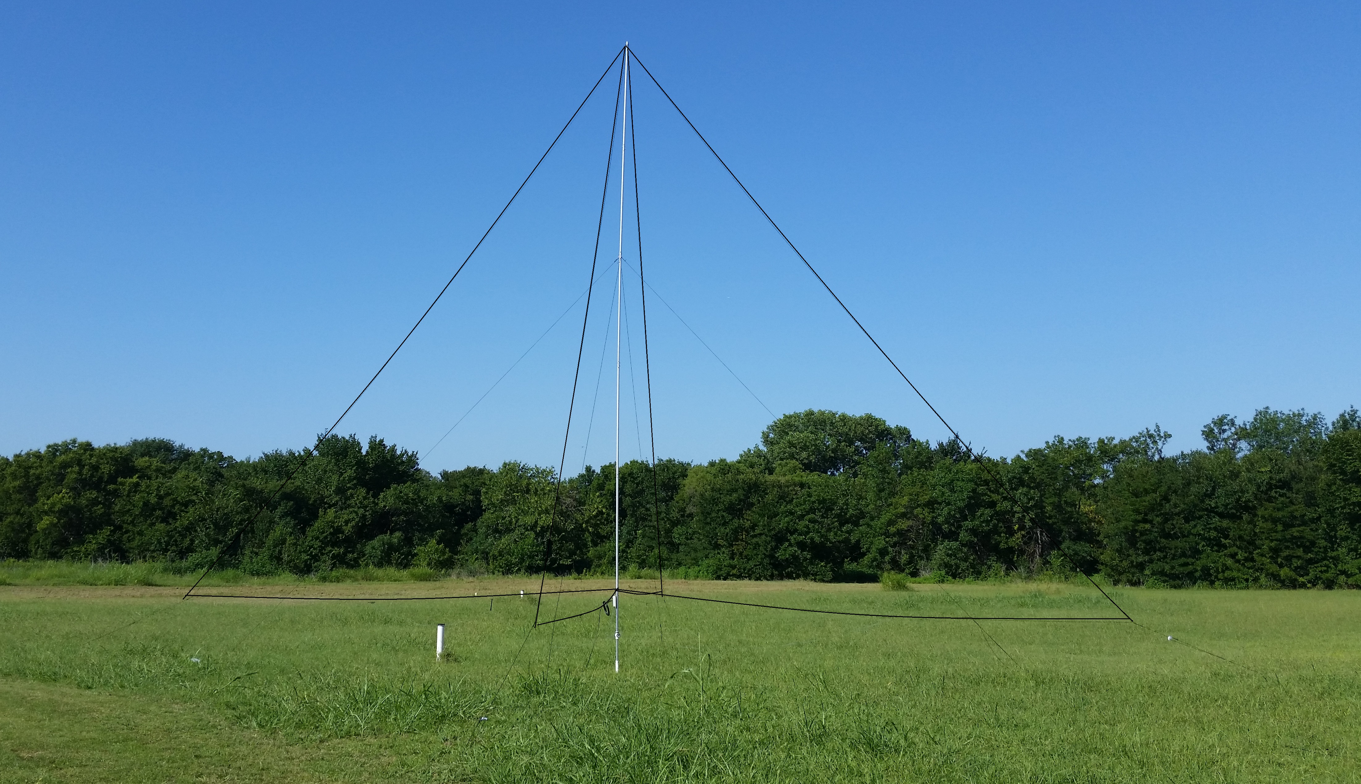
Introducing the Shared Apex Loop Array Mark-II version TM! Improved version, now with aluminum mast.
Three models to chose from:
- AS-SAL-30-Mark II - optimized for VLF, BCB, 160/80/40m DXing, 34'-2" feet (10.41
m) tall and approximately 47 feet x 47 feet (14.33 m x 14.33 m) square
footprint, click here to order
- AS-SAL-20-Mark II - optimized for LF, BCB and shortwave to 15 MHz, 22 feet
(6.71 m) tall and approximately 36 feet x 36 feet (11 m x 11 m) footprint, click here to order
- AS-SAL-12-Mark II - optimized for BCB, and 3 to 30 MHz, 16 feet (4.88 m)
tall, and approximately 26 feet x 26 feet (7.92 m x 7.92 m) square footprint, click here to order
For each of these models there is a "DX" version that does not include the mast, stakes and 15 V DC power supply, making it affordable by reducing the overseas shipping costs.
- AS-SAL-30-Mark II-DX, click here to order
- AS-SAL-20-Mark II-DX, click here to order
- AS-SAL-12-Mark II-DX, click here to order
There is also the SAL-EXP, the SAL experimenters kit, which includes only the Controller and the Combiner only, click here
Mast configurations for the three models, the red piece is an insulator: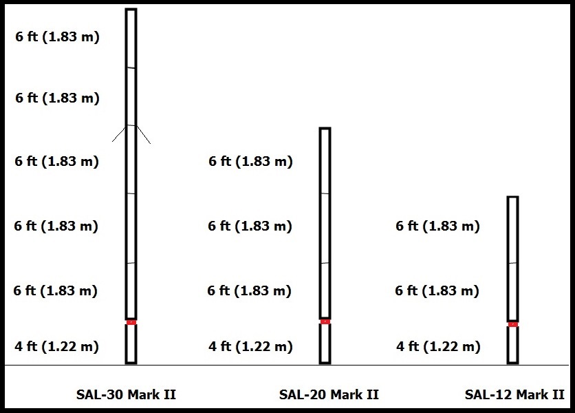
Footprints: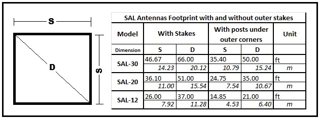
Without stakes: You can save around 8 feet (2.44 m) beyond the outer corners of the loops if instead of using the outer stakes you anchor the outer corners of the loops directly to non conductive posts (like 4" x 4" wooden posts).
Avoiding Animals, People, Vehicles and Machinery by raising the antenna higher above ground
You can elevate the antenna to avoid problems with deer, people or vehicles. Simulations show that the optimal height of the antenna's lower wires at a given frequency is one quarter wavelength, therefore there is room for improvement going up. The standard height of the old model was given by the effective height (44.5 inches or 1.13 m) of the mast sections used. The new model has a bottom section of 4 feet (1.22 m), you can add more aluminum to that bottom section and use non conductive poles for the outer corners of the loops if a higher minimum height above ground is needed.
How far from the transmit antenna and metallic structures?
To protect the MOSFETs (J309 or J310) in the pre-amplifier circuit located in the combiner from the RF field of a transmitting antenna on 160 m band with 1500 W the minimum distance recommended is 100 feet (30.48 m) further away is better. Please check on the Yahoo Group of SAL antenna users at the bottom of this page for the back-to-back diodes solution installed at the input of the pre-amp to protect the MOSFETs, you can learn and evaluate the cons, pros and opinions on this solution.
From sizeable metallic structures that may distort the pattern the minimum ideal would be one quarter wavelength (135 ft or 41.15 m on 160 m)
The coaxial cable feed line, how long can it be?
Until now, there are installations that have up to 1400 feet (426.72 m) of RG-6, as long as the voltage drop to the combiner leaves at least 12 V DC, the antenna will work. An RG-11 coaxial cable or the LMR-400-75 (the 75 ohm version of the LMR-400) would have less voltage drop than the RG-6 for longer runs. If we learn of a working longer RG-6 run we will update the information here.
Instructions Manuals Downloads
To download the manual for the SAL-XX-Mark II, click here
Click here to download the SAL software
For information on how to build your own mast for any of the three models of SAL-XX-Mark II, click here
To download the old SAL-XX manual (discontinued model with fiberglass mast), click here
To download the Japanese version of the old SAL-XX manual (translated by Katsuhiro "Don" Kondou - JH5GHM), click here
NOTE: The Japanese version of the manual is for the old SAL model but it is helpful for Japanese readers if you keep in mind that the difference with the new model is the replacement of the four vertical sides of the loops by a single conductor, shared by the four loops, made of aluminum.
Videos and Reviews
First video for the SAL-30 Mark II, click here
Performance of the SAL-30 at 1.7 MHz, click here
Reception comparison between a SAL-30 and the transmit antenna, click here
SNR: Hi-Z of 4 elements vs. SAL-30, click here
Working FT5ZM via long path on 80 m receiving with the SAL-30, click here
VE1ZAC complete review on his SAL-20 antenna, click here
For eham.net reviews on the SAL antenna, click here
Software downloads
Control software for the SAL antenna, click here


Screenshots of the control software windows. This software can be used to control the antenna installed at a remote location with an internet connection or a network connection or just control it from the screen of you computer at your operating position. NOTE: To access the ShackLan network of the Hamation controllers with your PC you need the ShackLan 4 USB interface (click here)
At www.hamation.com you can download the free software, "Control Center", that contains the software of the windows shown above and much more to control and share band data information for several daisy-chained Hamation controllers for selection of antennas, control of StackMatches, control of the several vertical antenna arrays like the Four Square, Triangle array, Two vertical antennas array, filter selection automation and more. You can define and name at convenience certain antenna combination as a virtual antenna on a Stackmatch, or on a vertical antennas array, define a primary and a secondary antenna -virtual or not- for a given band on RX and a different one for TX.